Key takeaways
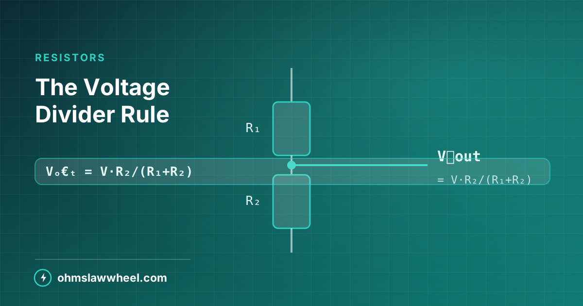
- Vₒ€ₜ = Vₙ × R₂ ÷ (R₁ + R₂)
- Only the ratio sets the output; the absolute values set the current.
- Any load in parallel with R₂ pulls the output down.
- Never use a plain divider to power something — only to sense or reference.
The rule itself
Two resistors in series across a supply. The output is taken from the junction between them, referenced to the bottom of R₂:
- Vₒ€ₜ = Vₙ × R₂ ÷ (R₁ + R₂)
It follows directly from Ohm's law. The same current flows through both resistors, so the voltage across each is proportional to its resistance — exactly the series behaviour covered elsewhere.
Worked example
12 V supply, R₁ = 10 kΩ, R₂ = 4.7 kΩ:
- Vₒ€ₜ = 12 × 4700 ÷ 14700 = 3.84 V
- Current: 12 ÷ 14700 = 0.816 mA
- Power in R₁: 0.816 mA² × 10 k = 6.7 mW — any part rating is ample
Ratio versus absolute value
10 kΩ / 4.7 kΩ and 1 kΩ / 470 Ω produce the same 3.84 V. What changes is the current drawn:
| R₁ | R₂ | Vₒ€ₜ | Current | Total power |
|---|---|---|---|---|
| 100 Ω | 47 Ω | 3.84 V | 81.6 mA | 979 mW |
| 1 kΩ | 470 Ω | 3.84 V | 8.16 mA | 98 mW |
| 10 kΩ | 4.7 kΩ | 3.84 V | 0.82 mA | 9.8 mW |
| 100 kΩ | 47 kΩ | 3.84 V | 0.08 mA | 1 mW |
Low values waste power continuously; high values are easily upset by load and by noise. Mid values are the usual compromise.
Voltage Divider CalculatorEnter the supply and both resistors to get the output voltage, current and power in each leg.
The loading problem
Connect a load across R₂ and it sits in parallel with it. The effective lower leg drops, and so does the output.
Worked loading example
Take the 10 k / 4.7 k divider above and connect a 4.7 kΩ load:
- Lower leg becomes 4.7 k ∥ 4.7 k = 2.35 kΩ
- Vₒ€ₜ = 12 × 2350 ÷ 12350 = 2.28 V
- The expected 3.84 V has fallen by 41%
The ten-times rule
Keep the load resistance at least ten times R₂ and the output sags by under 1%. For a hundred-times margin the error is negligible.
| Load ÷ R₂ | Output error | Verdict |
|---|---|---|
| ×1 | −41% | Unusable |
| ×10 | −6% | Marginal |
| ×100 | −0.7% | Good |
| ×1000 | −0.07% | Excellent |
Where dividers are the right answer
- Scaling a voltage for an ADC. A microcontroller input draws almost nothing, so loading is negligible.
- Sensor bridges. A thermistor or LDR as one leg turns resistance change into voltage change.
- Feedback networks. Setting the output of a regulator or op-amp.
- Biasing. Establishing a mid-rail reference for a signal stage.
Where they are the wrong answer
Never use a resistive divider to drop a supply for a real load. Regulation is nonexistent, efficiency is poor, and the output moves with every change in load current. Use a regulator or a converter instead.
Designing one in four steps
- Fix the ratio. R₂ ÷ (R₁ + R₂) = Vₒ€ₜ ÷ Vₙ.
- Choose a current. Around 100 µA to 1 mA suits most sensing work.
- Scale to preferred values. Pick the nearest E24 or E96 values that keep the ratio.
- Check the loading. Confirm the load is at least ten times R₂, and verify the dissipation.
Buffering the output
When the load is too heavy for a divider to feed directly, the standard answer is not a bigger divider — it is a buffer.
- Op-amp voltage follower. Its input draws almost nothing, so the divider stays unloaded, and its output can drive a real load. This is the usual solution for a reference voltage.
- Emitter follower. A single transistor gives useful current gain, at the cost of a diode drop.
- Dedicated reference IC. Where accuracy and stability matter, a shunt reference beats any resistor pair.
Sensor dividers
Putting a thermistor, LDR or potentiometer in one leg turns a resistance change into a voltage a microcontroller can read. Choose the fixed resistor close to the sensor's mid-range resistance — that places the steepest part of the response where you need the most sensitivity, and keeps the output comfortably inside the ADC range.
Tolerance stack-up
Two ±5% resistors can shift the ratio by up to about 10% in the worst case. For a reference or an ADC scaling network, specify ±1% parts — the cost difference is trivial and the accuracy improvement is five-fold.
The voltage divider calculator at Ohms Law Wheel reports the output, both currents and both dissipations, so you can test a candidate pair before ordering anything.
Frequently asked questions
What is the voltage divider formula?
Vₒ€ₜ = Vₙ × R₂ ÷ (R₁ + R₂), where R₂ is the resistor between the output tap and the reference rail.
Why does my voltage divider output drop when I connect something?
The load sits in parallel with R₂, lowering the effective lower leg and therefore the ratio. Keep the load at least ten times R₂ or buffer the output with an op-amp follower.
Can I use a voltage divider to power a circuit?
No. A divider has no regulation, so its output moves with load current and it wastes power continuously. Use a linear regulator or a DC-DC converter to supply a real load.