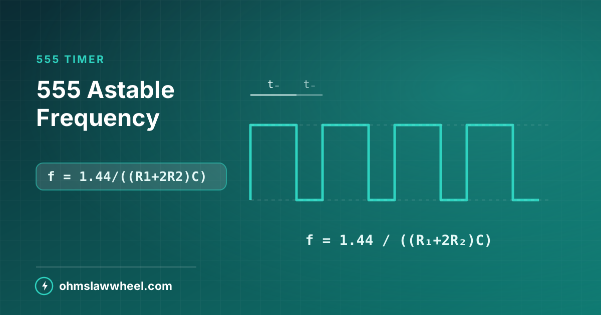
Key takeaways
- f = 1.44 ÷ ((R₁ + 2R₂) × C)
- The capacitor charges through R₁ + R₂ and discharges through R₂ alone.
- That asymmetry means the duty cycle is always above 50%.
- A diode across R₂ is the usual fix.
How astable mode works
In astable mode the 555 free-runs, with no trigger required. The timing capacitor charges toward the supply through R₁ and R₂ in series. At two-thirds of V₊₊ the internal comparator flips and the discharge pin pulls the junction of R₂ and C to ground. The capacitor now discharges through R₂ only, until it reaches one-third of V₊₊, and the cycle repeats.
Because charging goes through more resistance than discharging, the high period is always longer than the low period.
The formulas
- tₕₛₕₙ = 0.693 × (R₁ + R₂) × C
- tₗₔ₣ = 0.693 × R₂ × C
- T = 0.693 × (R₁ + 2R₂) × C
- f = 1.44 ÷ ((R₁ + 2R₂) × C)
- duty = (R₁ + R₂) ÷ (R₁ + 2R₂) × 100%
The 0.693 is ln(2), which comes from the capacitor charging between the one-third and two-thirds thresholds. Note that the supply voltage does not appear — frequency is independent of V₊₊, which is one of the chip's most useful properties.
Worked example
R₁ = 10 kΩ, R₂ = 47 kΩ, C = 1 µF:
- tₕₛₕₙ = 0.693 × 57000 × 1e−6 = 39.5 ms
- tₗₔ₣ = 0.693 × 47000 × 1e−6 = 32.6 ms
- T = 72.1 ms → f = 13.9 Hz
- Duty = 57 ÷ 104 = 54.8%
555 Astable CalculatorEnter R1, R2 and C for frequency, period, duty cycle and both half-times.
Component ranges
| Capacitor | Frequency | Period | Typical use |
|---|---|---|---|
| 100 µF | 0.139 Hz | 7.2 s | Slow flasher |
| 10 µF | 1.39 Hz | 720 ms | LED blinker |
| 1 µF | 13.9 Hz | 72 ms | Visible flicker |
| 100 nF | 139 Hz | 7.2 ms | Low audio tone |
| 10 nF | 1.39 kHz | 720 µs | Audible beep |
| 1 nF | 13.9 kHz | 72 µs | High tone, clock |
Practical component limits
- R₁ minimum 1 kΩ — the discharge transistor must survive the current.
- Total resistance below about 1 MΩ — above that, leakage and bias current spoil accuracy.
- Avoid electrolytics for timing where possible; their tolerance can be −20/+80%.
- Keep C above 1 nF — stray capacitance becomes significant below that.
The duty cycle problem
Because charging uses R₁ + R₂ and discharging uses only R₂, the standard circuit can never reach 50%. Making R₁ very small approaches it, but R₁ must stay above about 1 kΩ.
Three fixes
- Diode across R₂. Charging bypasses R₂ through the diode, so tₕₛₕₙ = 0.693 R₁C and tₗₔ₣ = 0.693 R₂C. Equal resistors then give almost exactly 50%.
- Divide by two. Run the 555 at double frequency and follow it with a flip-flop for a guaranteed 50%.
- Make R₁ ≪ R₂. With R₂ = 100 kΩ and R₁ = 1 kΩ, duty is 50.2% — close enough for most purposes.
Accuracy and stability
The formula assumes ideal components. In practice several factors move the real frequency away from the calculated one.
- Capacitor tolerance dominates. An electrolytic at −20/+80% swamps every other error, so use film or ceramic C0G for anything that must hold frequency.
- Resistor tolerance adds its own few percent; E24 at ±5% is usually the limiting factor after the capacitor.
- Temperature drift affects the capacitor far more than the chip.
- Supply noise couples into the threshold comparators, which is why the decoupling capacitors matter.
Bipolar versus CMOS
The original bipolar 555 sinks a large current spike from the supply on every output transition, which is why it needs solid decoupling. CMOS versions such as the 7555 draw a fraction of the current, run from lower supplies and reach higher frequencies, at the cost of much lower output drive. For a battery circuit the CMOS part is almost always the better choice.
Design routine
- Choose C from the frequency range in the table above.
- Pick the duty cycle, which fixes the ratio of R₁ to R₂.
- Solve for the resistors from the frequency formula.
- Round to E24 values and recalculate the actual frequency.
- Add a 100 nF decoupling capacitor at pin 8 and 10 nF at pin 5.
For single pulses rather than continuous oscillation, see the monostable guide, and check any design with the 555 astable calculator.
Frequently asked questions
What is the 555 astable frequency formula?
f = 1.44 ÷ ((R₁ + 2R₂) × C), with resistance in ohms and capacitance in farads. The result is independent of supply voltage.
Why can a 555 astable not reach a 50% duty cycle?
The capacitor charges through R₁ + R₂ but discharges through R₂ alone, so the high time is always longer. Adding a diode across R₂ equalises the two paths.
What is the maximum 555 astable frequency?
A standard bipolar 555 is practical to a few hundred kilohertz. CMOS versions such as the 7555 reach well above 1 MHz with lower supply current.