Key takeaways
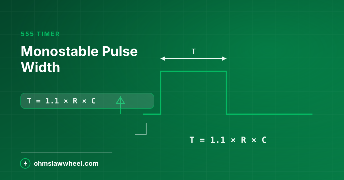
- T = 1.1 × R × C
- Triggered by pulling pin 2 below one-third of V₊₊.
- The trigger pulse must be shorter than the output pulse.
- The standard circuit cannot be retriggered mid-pulse.
How monostable mode works
The circuit has one stable state: output low, timing capacitor held discharged. A negative-going edge on the trigger pin flips the internal latch, the output goes high, and the capacitor starts charging through R.
When the capacitor reaches two-thirds of V₊₊, the threshold comparator resets the latch. The output falls, the capacitor is discharged, and the circuit waits for the next trigger. This is why it is called a one-shot.
Where 1.1 comes from
The capacitor must charge from zero to two-thirds of the supply. Solving the exponential charging equation for that point gives ln(3) = 1.0986, rounded to 1.1 in practice. As with astable mode, the supply voltage cancels out — the pulse width is the same on 5 V or 15 V.
Choosing components
| R | C | Pulse width | Typical use |
|---|---|---|---|
| 10 kΩ | 1 nF | 11 µs | Pulse stretching |
| 10 kΩ | 100 nF | 1.1 ms | Switch debounce |
| 100 kΩ | 100 nF | 11 ms | Short indicator flash |
| 100 kΩ | 1 µF | 110 ms | Relay pulse |
| 100 kΩ | 10 µF | 1.1 s | Stairwell light |
| 470 kΩ | 100 µF | 51.7 s | Long delay |
| 1 MΩ | 470 µF | 8.6 min | Fan run-on |
Practical limits
- R between 1 kΩ and 1 MΩ. Below that the discharge transistor struggles; above it, leakage dominates.
- Beyond a few minutes, accuracy collapses. Electrolytic leakage can prevent the capacitor from ever reaching the threshold.
- Use film capacitors where timing accuracy matters. Electrolytic tolerance alone can be −20/+80%.
- Round to preferred values and recalculate rather than chasing an exact resistance.
555 Monostable CalculatorEnter R and C for the exact pulse width, or work backwards from a target time.
Triggering correctly
If the trigger input is held low for longer than the timed period, the output stays high until the trigger releases. The pulse is then set by the input, not by RC. Always AC-couple a long trigger with a small capacitor and a pull-up resistor.
- Pin 2 must be pulled below ⅓ V₊₊ — 1.67 V on a 5 V supply.
- Hold pin 2 high with a 10 kΩ pull-up when idle; a floating trigger causes random firing.
- A 100 nF series capacitor with that pull-up turns any long low into a short edge.
- Tie the reset pin (4) to V₊₊ unless you are actively using it.
Retriggering
The standard circuit ignores triggers that arrive while the output is already high — it is non-retriggerable. Some applications want the opposite:
- Non-retriggerable (default) — suits debouncing and fixed-length pulses.
- Retriggerable — add a transistor to discharge the timing capacitor on each trigger, so the pulse restarts. Useful for motion-sensor lighting that should stay on while movement continues.
Common applications
- Switch debounce. A 10-50 ms pulse masks contact bounce entirely.
- Missing-pulse detector. Retriggerable mode with T longer than the expected interval.
- Timed relay. Drive the coil through a transistor, with a flyback diode across it.
- Delayed switch-off. Fan run-on, stairwell lighting, courtesy lamps.
Output current
A bipolar 555 sources or sinks up to 200 mA, which is enough to drive an LED directly — still through a series resistor, as covered in our LED resistor guide. For anything heavier, use a transistor or a relay.
Improving timing accuracy
The 555 itself is stable; the timing components rarely are. Where the exact period matters, work on those first.
- Choose the capacitor carefully. Film or C0G ceramic holds tolerance; general ceramic and electrolytic do not.
- Favour a larger R and a smaller C. Resistors are available at ±1% far more cheaply than capacitors are.
- Add a trimmer. A fixed resistor plus a small preset lets you calibrate the period once and forget it.
- Keep the timing node clean. Flux residue across pins 6 and 7 forms a leakage path that shortens long periods unpredictably.
When to use something else
For periods beyond a few minutes, or where accuracy must survive temperature changes, a microcontroller with a crystal or an RC oscillator calibrated in firmware is both cheaper and far more precise than a 555 with a very large capacitor.
Design routine
- Choose C from the table nearest your target time.
- Rearrange: R = T ÷ (1.1 × C).
- Round to the nearest preferred value and recalculate T.
- Add a 100 nF decoupling capacitor at pin 8 and 10 nF at pin 5.
- Confirm the trigger is a short edge, not a level.
Verify the numbers with the 555 monostable calculator, and see the astable guide if you need a continuous train instead of a single pulse.
Frequently asked questions
What is the 555 monostable pulse width formula?
T = 1.1 × R × C, with R in ohms, C in farads and T in seconds. The 1.1 is ln(3), from charging the capacitor to two-thirds of the supply.
Why does my 555 output stay high longer than calculated?
The trigger input is almost certainly being held low past the end of the timed period. AC-couple the trigger with a small series capacitor and a pull-up resistor so only the edge reaches pin 2.
Can a 555 monostable be retriggered during its pulse?
Not in the standard circuit — triggers during the output pulse are ignored. Adding a transistor to discharge the timing capacitor on each trigger makes it retriggerable.